


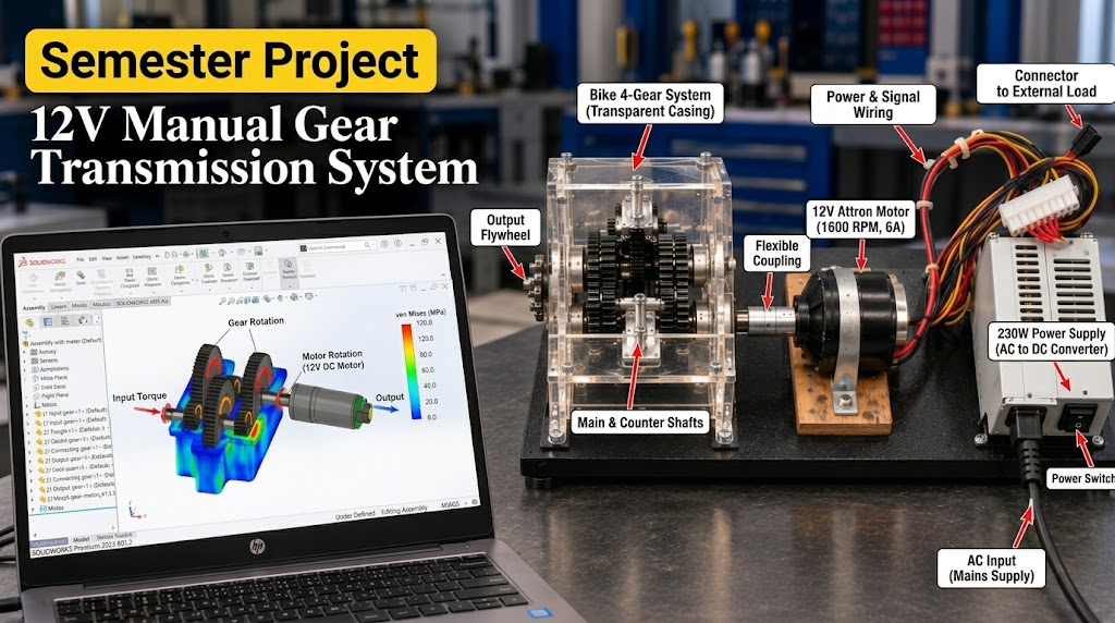
12V Manual Gear Transmission System
Project Overview
This project presents the design, construction, and analysis of a manually operated 12V gear transmission system engineered to demonstrate the fundamental principles of gear mechanics, torque multiplication, and power transmission. By replicating a real-world multi-gear transmission mechanism on a smaller scale, the system simulates actual gear-changing processes to evaluate the direct impact of varying gear ratios on output speed and torque. It serves as a practical bridge between theoretical mechanical concepts and real-world automotive and industrial applications.
Key Components & Tools
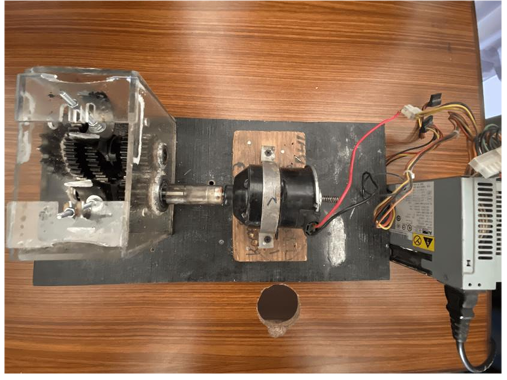
- Mechanical Hardware: A 4-gear bike transmission system, splined main and counter shafts, ball bearings for friction reduction, a manual gear slider, and an output flywheel to stabilize rotational inertia.
- Electrical Hardware: A 12V DC Attron Motor (1600 RPM, 6 Amperes) acting as the primary drive, powered by a 230W AC-to-DC power supply.
- Measurement & Testing: A laser tachometer was utilized for precise experimental RPM data acquisition.
- Software Stack: SolidWorks was employed for 3D CAD modeling, component assembly, and Static Stress Analysis.
Design & SolidWorks Simulation (Stress Analysis)
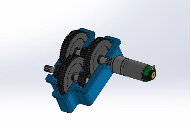
- A comprehensive 3D CAD model was developed in SolidWorks, ensuring the precise alignment of gears, shafts, and bearings prior to physical assembly.
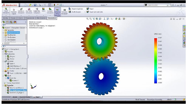
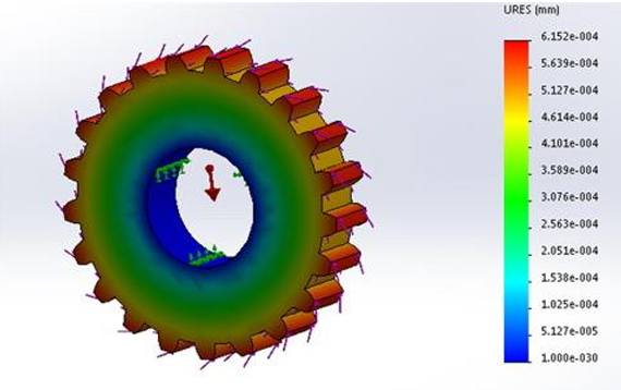
- Static Stress Analysis was conducted to predict structural behavior under torque loading, specifically evaluating stress concentrations at gear teeth contact points and root areas.
- Simulations analyzed the inverse relationship between face width and bending deformation, allowing for optimized design parameters that enhance durability and mechanical efficiency.
Experimental Testing & Calculations
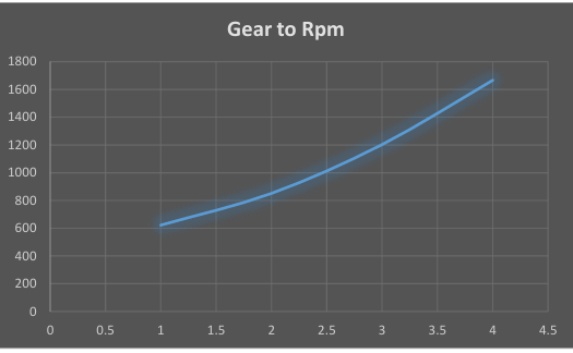
- Practical experiments validated the mechanical principle that higher gears (lower ratios) increase output speed while decreasing torque, and vice versa.
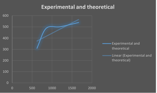
- Experimental output speeds were successfully recorded across four gear stages using a laser tachometer: Gear 1 (309 RPM), Gear 2 (487 RPM), Gear 3 (501 RPM), and Gear 4 (538.9 RPM).
- Theoretical RPM and torque calculations were compared against empirical data. The analysis successfully identified and quantified mechanical energy losses attributed to bearing friction, motor loading effects, and transmission inefficiencies.
Conclusion
This project effectively demonstrates the core principles of mechanical engineering and gear dynamics. By successfully designing, assembling, and testing a manual transmission system, it provides a highly reliable, hands-on framework for understanding torque, power transmission, and efficiency losses in mechanical systems.
